悬臂皮带运输机常见故障分析与处理(英文稿)
Common
Fault Analysis For Belt Conveyer
By
Li Yimin Aug 11.2008
Bulk-OnWeb www.bulkcn.com
Belt conveyers as continuous bulk material conveying machinery have been
widely used in the world, electric power plants, metallurgical industry and
foodstuff industry as well as in bulk material conveying machinery such as ship
loader and bucket-wheel stacker-reclaimer. In the purchase, design, manufacture,
erection and operation of this kind of equipment, some of new users are not
familiar with them. Common fault causes and their handling methods of this kind
of equipment are analyzed and described herein as a matter of experience in the
past years and from the point of view of users.
1. Handling of belt deviation
of belt conveyer: The belt deviation of belt conveyer during operation is the
most common fault. To handle this type of fault, emphasis should be placed on
the dimensional accuracy of erection and the routine maintenance. There are
several kinds of causes. The differential treatment should be made according
to the different causes.
1.1
Adjustment of carrying roller set: If the belt of belt conveyer is
deviated in the middle of the whole belt conveyer, the position of carrying
roller set is adjusted. During the manufacture, the mounting holes on both sides
of carrying roller set are machined to slots for the convenience of adjustment.
For the specific adjusting methods, see Fig. 1. The specific method is that when
the belt is deviated from the side, that side of carrying roller set should be
moved forwards the direction of travel, or the other side moved backward the
direction of travel. If the belt is deviated from the upper direction as shown
in Fig. 1, the bottom position of carrying roller set should be moved to the
left side and the upper position of carrying roller set is moved to the right
side. 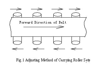
1.2 Installation of
self-aligning carrying roller set: There are many types of self-aligning
carrying roller sets such as intermediate rotating shaft type, four-link type
and edging roll type. The principle is that by utilizing blocking or rotating
the rollers in the direction of horizontal plane, the rollers are blocked by
rotating or the lateral thrust is produce to make the belt be automatically
aligned so as to attain the object of adjustment of belt deviation. It is
feasible, in general, to use this method when the whole length of belt of belt
conveyer is shorter or the belt conveyer is operated in the bidirection. The
causes are that the shorter belt conveyer is easier to be deviated and it is not
easily adjusted. Therefore, this method is not used for the longer belt
conveyers because use of self-aligning carrying roller sets can have certain
influence on the service life of belt.
1.3 Adjustment of positions
of head roll and bend pulley: Adjustment of head roll and bend pulley is a key
link of adjustment of belt deviation. Since there are at least 2 to 5 pulleys
in one belt conveyer, the mounting position of all the pulleys must be perpendicular
to the central line along the length of belt conveyer. If the deviation is too
large, the belt deviation occurs of necessity. The adjusting method is similar
to that of carrying roller set. For head pulleys, if the belt is deviated from
the right side of pulley, the bearing block at the right side should be moved
forward and if the belt is deviated from the left side of pulley, the bearing
block at the right side should be moved forward. For corresponding pulleys,
the bearing block at the left side can be also moved backward or the bearing
block at the right side moved backward. The adjusting method of tail pulleys
is just opposite from that of head pulleys. For the adjusting method, see
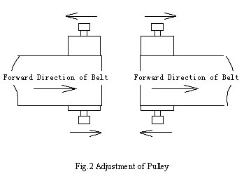
Fig. 2. The pulleys are repeatedly
adjusted till the belt is adjusted to the expected position. It is preferable
to make the mounting position accurate before adjustment of head rolls or bend
pulleys.
1.4 Adjustment of belt tensioning device: Adjustment of belt tensioning device is a very important link
of adjustment of belt deviation of belt conveyer. Two bend pulleys on the top
of counterweighted tensioning device should be not only perpendicular to the
direction of the belt along length but also to the gravity vertical, i.e. it
is ensured that the shaft center line is horizontal. When the screw tensioning
device or hydraulic tensioning device is used, two bearing blocks of tensioning
pulley should be synchronously translated so as to ensure that the axial line
of pulley is perpendicular to the longitudinal direction of belt. The specific
adjusting method of belt deviation is similar to the adjusting method of pulleys.
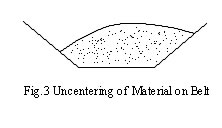
1.5
Influence of material receiving position at the transfer point on the belt
deviation: The material receiving position at the transfer point has a great
influence on the belt deviation, especially when the projection of two belt
conveyers in the horizontal plane. The relative height of the upper belt
conveyer and lower belt conveyer at the transfer point should be normally taken
into consideration. The lower the relative height the greater the horizontal
velocity component of material and also the greater the lateral impact on the
lower layer of belt. In addition, the material is difficult to center so as to
make the material at the cross section of belt be skew and finally lead to belt
deviation. If the material is deviated from the right side, the belt will be
deviated from the left side, vice versa. In the course of design, the relative
height of two belt conveyers is increased as practically as possible. The form
and dimension of the upper hopper and the lower hopper, chute etc. of bulk
material mobile conveying machinery which are limited by space should be more
carefully taken into consideration. In general, it is applicable for the width
of chute being about 2/3 of that of belt. In order to reduce or avoid the
belt from being deviated, the baffles can be increased to block the material and
change the falling direction and position of material. For the uncentering of
material on the belt, see Fig. 3.
1.6 Adjustment of belt deviation
of bi-directional belt conveyer: Adjustment of belt deviation of
bi-directional belt conveyer is relatively more difficult than that of
belt deviation of one-way belt conveyer. During the specific adjustment,
the adjustment should be done from one direction, and then from the
other. During adjusting, it must be carefully observed to the
relationship between the travel direction of belt and the tendency of
belt deviation. The adjustment should be done one by one. Firstly
emphasis should be placed on adjustment of head rolls and bend pulleys.
Secondly emphasis is placed on adjustment of the carrying rollers and
the material receiving point. In addition, it should be noted that the
load is uniformly distributed at the section of the belt along the
length when the belt is at the vulcanized joints. When the leading chain
is used for traction, the load at both sides should be distributed as
equally as possible.
2. Material spillage on belt conveyer: Material spillage on the belt conveyer is a general character.
The causes are embodied in several aspects. Therefore, emphasis is placed on
strengthening the routine maintenance.
2.1 Material spillage at
transfer point: Material spillage occurs mainly at the transfer points such
as material receiving hopper and chute. If serious overload occurs on the belt
conveyer, the rubber skirt plate of chute of belt conveyer can be damaged. Since
the steel plate of chute is far from the rubber skirt plate in the design, the
material will be flown out of the chute. The problem can be solved by controlling
the conveying capacity and strengthening the routine maintenance.
2.2 Material spillage
at the concave section of belt during hanging: The belt at the concave section
is floated when the radius of curvature is smaller. At this tome the belt in the
form of trough has been changed because the belt has been deviated from the
trough carrying roller set. In that case, the angle of trough becomes small so
as to make part of the material be split out. Therefore, the bigger radius of
curvature at the concave section is used as practically as possible in the
design in order to avoid the material spillage. If the concave section is
designed according to the section of transition without arc in the mechanical
traveling ship loader or stacker-reclaimer in order to shorten its tail car, the
material spillage may easily occur when there is less room for selection of belt
width.
2.3 Material spillage
during the belt deviation: The material spillage occurs during the belt
deviation because two edges of belt have changed in height during operation,
i.e. one edge is higher and the other is lower. The material is split out from
the lower edge. The handling method is to adjust the belt deviation.
3. Abnormal noise:
When the belt conveyer is operated, it could sound abnormally from its drive,
head roll, bend pulley or carrying roller set. The failure of equipment can be
determined according to the abnormal noise.
3.1 Noise occurs when
the carrying roller being seriously deviated: When the belt conveyer is
operated, the abnormal noise could be produced and accompanied by periodic
vibration, especially in the return rolls. The longer the roll and the heavier
the deadweight, the higher the noise. There are mainly two causes for noise: one
is that the wall thickness of seamless pipe made of carrying roller is
non-uniform so as to produce the greater centrifugal force and the other is that
during machining, the center of holes of bearing at both ends is greatly
deviated from the center of top circle so as to produce the greater centrifugal
force. The rolls can continue to use in case the bearings have not been damaged
and the noise is allowed to exist.
3.2 Noise occurs when two
shafts of coupling being not coaxial: The abnormal noise is produced from the
coupling between the high-speed shaft of motor in the drive and that of reducer
or from the coupling with brake wheel, it is also accompanied by the vibration
that is identical with the rotational frequency of motor. If the noise is produced,
the position of motor or reducer is adjusted in time in order to avoid the rupture
of input shaft of reducer.
3.3 Abnormal noise of bend
pulley and head roll: When the bend pulleys and head rolls are operated normally,
the noise is very low. If the abnormal noise is produced, the bearing, in general,
may be damaged. If the cackle is produced from the bearing block, the bearing
must be replaced.
4. Rupture of
shaft of reducer: The rupture of shaft of reducer generally occurs at the
high-speed shaft of reducer. The usual fault is that the first-stage shaft of
reducer is used as the high-speed shaft of vertical bevel gear shaft. There are
mainly two causes for shaft rupture as follows.
4.1 Inadequate design
strength of high-speed shaft of reducer: This fault, in general, occurs at the
shaft shoulder. Because the transient round angle exists at this place, it is
subjected to fatigue damage. If the round angle is too small, the rupture of
shaft of reducer can occur in the short time. After shaft rupture, the fracture
is generally flush. If this fault is found out, the reducer should be replaced
or the design of reducer should be modified.
4.2 High-speed shaft
being non-axial: When the high-speed shaft of motor is non-axial, the radial
load will be increased on the input shaft of reducer so as to increase the
bending moment on the shaft. If the shafts are operated in such a way for a long
time, the shaft rupture could occur. During installation and maintenance, the
position of shaft should be carefully adjusted in order to ensure that the two
shafts are aligned. In most cases, the rupture of motor shaft can not occur,
because the material used for motor shaft is #45 steel, the motor shaft is
thicker and has good stress concentration.
4.3 Rupture of shaft
in case two motors are used: The double-motor drive means that two reducers and
two motors are installed on one head roll. When there is less room for design or
selection of high-speed shaft of reducer, the shaft rupture easily occurs. In
the past years the hydraulic coupling was not used in the drive of belt
conveyer, so the failure easily occurred. The cause was that it was difficult to
ensure that the speeds were synchronous and the loads uniformly distributed. Now
the hydraulic couplings have been used in most of the belt conveyers, so the
shaft rupture does not frequently occur, but it should be noted that the
hydraulic coupling can not be filled with excess quantity of oil during
operation so as to make it have an effect on limitation of moment of force and
increase the service life of hydraulic coupling.
5. Shorter service life of
belt: The service life of belt and the service modes are related
to the quality of belt. It should be ensured that the cleaners are operated
reliably and in good order when the belt is operated. There is not any material
on the return belt. If the above can not be guaranteed, the material on the
return belt will enters into the head roll or the bend pulley along with the
return belt. The belt will be damaged due to the material on the surface of
belt, resulting in damage of the vulcanized rubber layer on the surface of pulley,
breach of the belt and decrease of the service life of belt. The manufacturing
quality of belt is the problem the users relatively give attention to. After
the selection of a model of belt, its manufacturing quality should be also taken
into consideration. The belts can be inspected by the national specialized institution
of quality determination. The appearance inspection is carried out conventionally
to see whether the crazing and aging exist and the resting period is over long
after manufacture. One of the above occurs, the belts should not be purchased.
The fissured belt to be initially found will be, in general, damaged in a short
time.
6. Influence of radius of
curvature at the convex-concave section of belt on belt conveyer
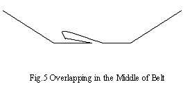
6.1 Arch camber at the convex section of belt in the
middle of cross section: The arch camber often occurs at the convex
section in the middle of cross section and the belt will be pleated, see Fig. 4.
After the overlapped
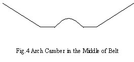
belt enters into the bend
pulley or head roll, the extent of damage of belt aggravated. The main causes
for arch camber and overlapping are that the difference between the values of
tensile force in a unit of length at the cross section of belt in the middle and
on the outside is oversized so that the belt is slid into the middle to form the
arch camber or overlapping. The magnitude of difference value of tensile force
in a unit of length is related to the radius of curvature at the convex section
and the trough angle of carrying roller. The bigger the trough angle, the
smaller the radius of curvature at the convex section and the severer the arch
camber and overlapping. When the trough angle of belt conveyer is equal to and
more than 40 degrees, the arch camber and overlapping can occur even at the
transition section of trough angle of head or tail roll which is run at the
straight section. At this time the trough angle should be reduced or the length
of transition section increased so as to make the trough angle of belt be
transited. For the belt conveyer at the convex section, the radius of curvature
at the convex section should be increased as practically as possible and the
trough angle of roll reduced in the condition that the conveying capacity is
met.
6.2 The belt at the
convex section being seized between flat roll and web roll: The belt being
seized between the flat roll and the web roll in the carrying roller set may
generally occur in the bulk material mobile
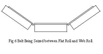
conveying machinery such as
ship loader and stacker-reclaimer. The belt seizure may easily occur when the
cantilever at the root position of cantilever beam of such equipment is pitched
downward. At this time it corresponds to the convex section occurring on the
belt. The size required for the radius of curvature at the convex transition
section can not be easily met because it is limited by the size of geometric
position. The belt being seized between the flat roll and the web roll in the
carrying roller set can occur only when the belt at the root of cantilever is
passed through one or two carrying roller sets to form the convex section. The
method of resolution is that the convex section formed by the original one or
two carrying roller sets is changed to that formed by four or five carrying
roller sets. For example, the belt conveyer is horizontally arrange at its rear,
the cantilever is pitched downward at the angle of 12 degrees at its fore and
the convex section is changed at the angle of 12 degrees. If five carrying
roller sets are used to transit the angle change in this place, the belt is just
buckled six times to attain the object of pitching downward at the angle of 12
degrees. The belt is buckled once at the angle of 2 degrees. After modification,
the belt being seized between the flat roll and the web roll in the carrying
roller set can not occur no longer. The design of four-link lever or follow-up
frame can be used for the base of roller carrier in the transition place which
position of angle is changed.
6.3 Bouncing and deflection
of belt by the wind at the concave section when starting:
If there is not any material on the belt when the belt conveyer is started,
the belt will be bounced at the concave section and displaced by the wind in
windy weather. Therefore, it is preferable that the pressure rollers are provided
at the concave section to avoid the belt from being bounced or displaced by
the wind.
7. Slipping of belt
7.1 Slipping of belt of belt
conveyer with counterweighed tensioning device: When the belt is slid in the
belt conveyer with counterweighted tensioning device, it can be solved by adding
the balance weights till the belt can not be slid. However, the balance weights
should not be excessive in order to avoid the belt from being subjected to
unnecessary oversized tensile force, thus resulting in decrease of the service
life of belt.
7.2 Slipping of belt of belt
conveyer with screw tensioning device or hydraulic tensioning device: The tensioning travel can be adjusted to increase the tensile
force when the belt is slid in the belt conveyer with screw tensioning device
or hydraulic tensioning device. At this time, however, a section of the belt
can be cut out for re sulfurzation when the tensioning travel is not enough
or the belt is permanently deformed.
Brief summary: The belt conveyers are
general-purpose mechanical equipment. They have been operated by the users for
many years. However, the maintenance of belt conveyers must be done at regular
intervals. Because of limitation of the length of a piece of writing, it is
difficult indeed to include all contents in one article. The experience with
operation and maintenance of belt conveyer can be gradually accumulated through
routine work. We hope that this text will be helpful for the users of belt conveyer.
(未经著作权人和本站的书面许可不可转载和使用本稿件)
返回首页
返回散料机械技术论文